Hardware
Case Parts
The case consists of the following parts:
The Two Halves are the chassis of MNT Pocket Reform, milled from sand-blasted and anodized 6061 aluminum. The top half houses the motherboard and the display, while the bottom half contains the keyboard, the batteries, and the charger.
The Top Back Cover: is made from PCB material and serves as a heatsink.
The Bottom Back Cover: is made from PCB material and displays regulatory information.
The Display Frame is made from PCB material. It encloses the display and the upper half of the hinges.
The Keyboard Frame is milled from sand-blasted and anodized 6061 aluminum. It comprises the speakers and the display bezel.
The Port Covers are located on the top half and give access to a variety of ports that can be used to connect MNT Pocket Reform to other devices.
For easy (dis)assembly, Pocket Reform uses M2 screws with Phillips-head everywhere—with one exception: M4x5 on the top half of the hinges.
Two Halves
The top half contains the actual computer and the display. That’s also why the ports are located at the sides of the top half.
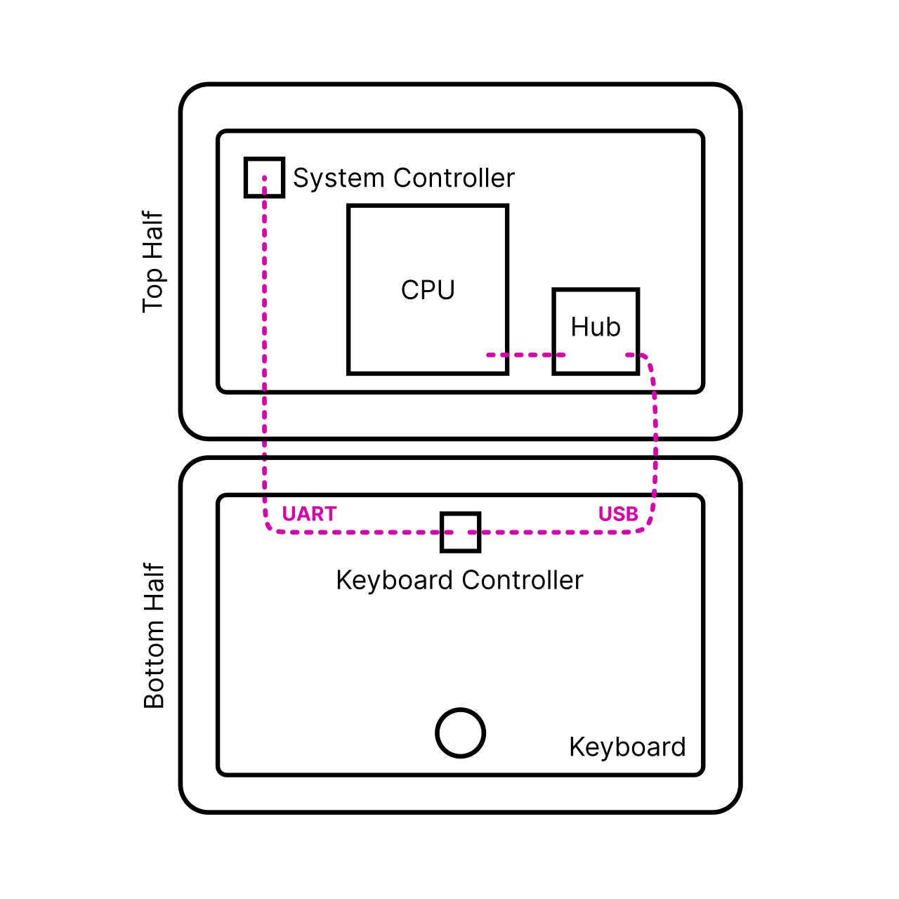
How are the two halves communicating? The keyboard (and its separate OLED display) are a direct user interface to the motherboard’s system controller and in turn, the power system—independently from the core computer part of the system. This way, you can always directly control the core system’s power and check on the batteries and charging level, even when the CPU is off. This architecture facilitates a convenient upgrade process of your older processor modules to new ones or to change your operating system, for example.
Technically, this works by decoupling the system control from the USB functionality of the input device. The keyboard and the trackball are combined into a single unified module in Pocket Reform. This unified module talks to the motherboard’s system controller via a dedicated UART and is always supplied with 3.3V standby power. It has a secondary connector for its USB function. This USB line is routed to the CPU module via a USB hub on the motherboard, and it is only active when the CPU itself is powered and active.
Top Half
The top half is made of anodized milled aluminum and houses the actual computer, i.e. the motherboard with its processor module, and the display. Additional parts are mounted to it:
Switch board with headset and standby power switch
Mono speaker
Port covers
Keyboard frame and display frame
Upper half of the hinges
If you open the top half of Pocket Reform you will encounter various internal cables. Here is what they do:
2-pin JST-SH (4 cm) cable: connects the standby power switch to the motherboard
5-pin JST-SH (4 cm) cable: connects the headset jack (headphone and microphone signals) to the motherboard
2x 4-pin JST-SH (8 cm) cables: connect the keyboard module’s USB and UART ports to the motherboard, through the hinges
2x 4-pin JST-PH (22 cm) cables: connect the charger module’s power port to the motherboard’s 9-pin JST-PH power connector (split into a ground and a voltage cable)
MIPI-DSI FPC cable: connects the display to the motherboard
Bottom Half
The bottom half is also made of anodized milled aluminum and contains several components:
Keyboard/trackball module and OLED display on the front side
3D printed (SLA) battery holders on the back side (mounted to it with M2 screws)
Two 606090 Li-ion batteries in total (one on each side)
Charger board in the middle between the batteries
Bottom half of the hinges
Display Frame
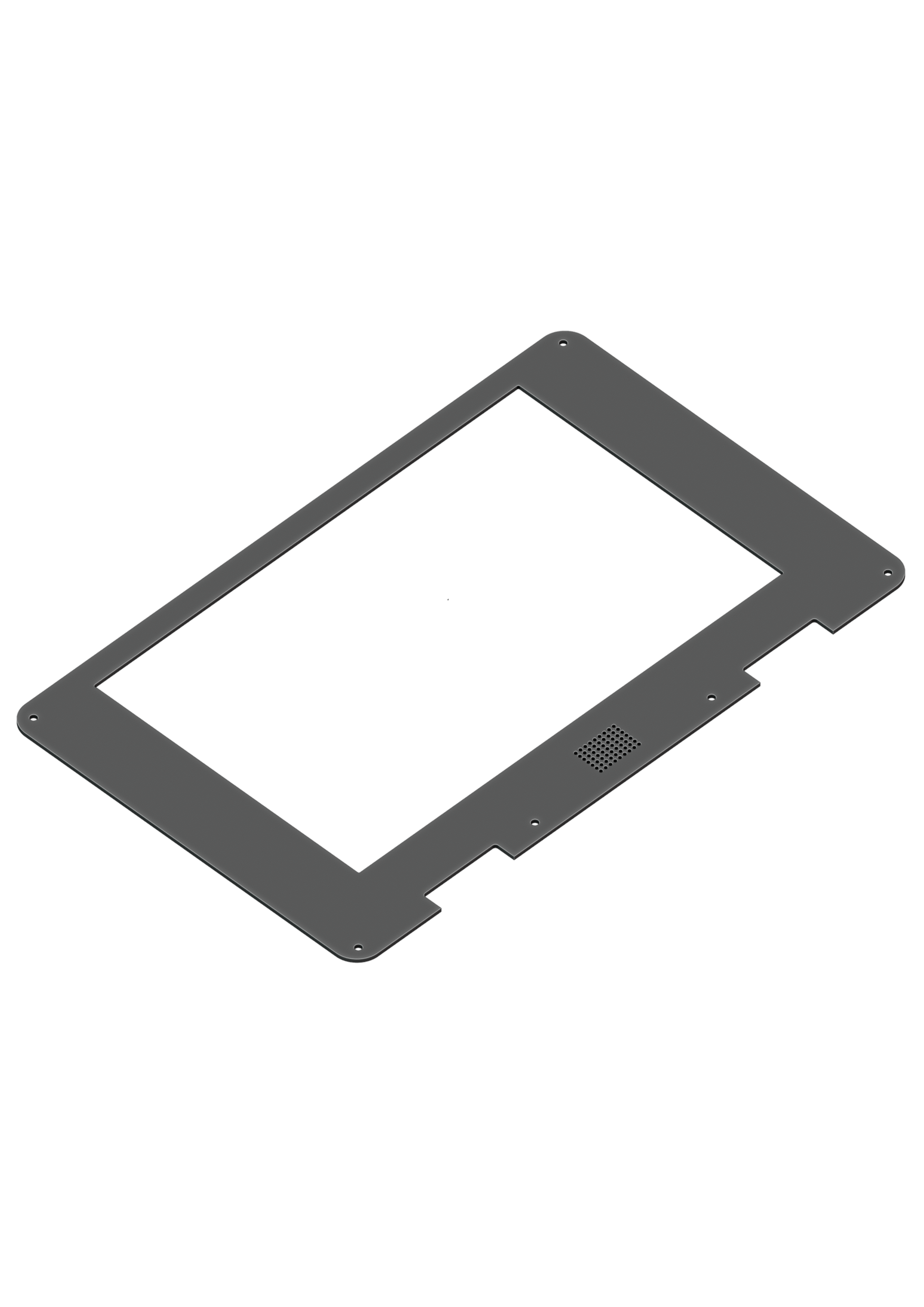
The display frame is a 1.2 mm PCB and acts as a bezel for the display and the speaker. It is attached with 6 M2 screws.
Top Back Cover
The top back cover is a 1.2 mm PCB that covers the motherboard. There is a large exposed copper area in the middle of the cover. It serves as the heatsink and has to be thermally attached to the CPU processor module using a square of a 2 mm thick thermal pad. It is attached with 7 M2 screws.
The areas of the top back cover that are free from copper (on the inside) are meant for attaching antennas such as Wi-Fi, Bluetooth or LTE. It’s recommended to use the area closer to the ports for Wi-Fi, so that there is no interference with the display cable.
Keyboard Frame
The keyboard frame is a 1.2 mm thick anodized milled aluminum plate that acts as the bezel for the keyboard, trackball, and the OLED display. It is attached with 4 M2 screws.
Bottom Back Cover
The bottom back cover is a 1.2 mm PCB that covers the batteries and the charger. It is attached with 6 M2 screws.
Port Covers
The Port Covers are two 1 mm thick PCBs that cover the side openings of the Top Half (mounted with two black M2x5 countersunk screws each). You can exchange these to fit a future motherboard or an expansion that requires a different port layout.
Motherboard
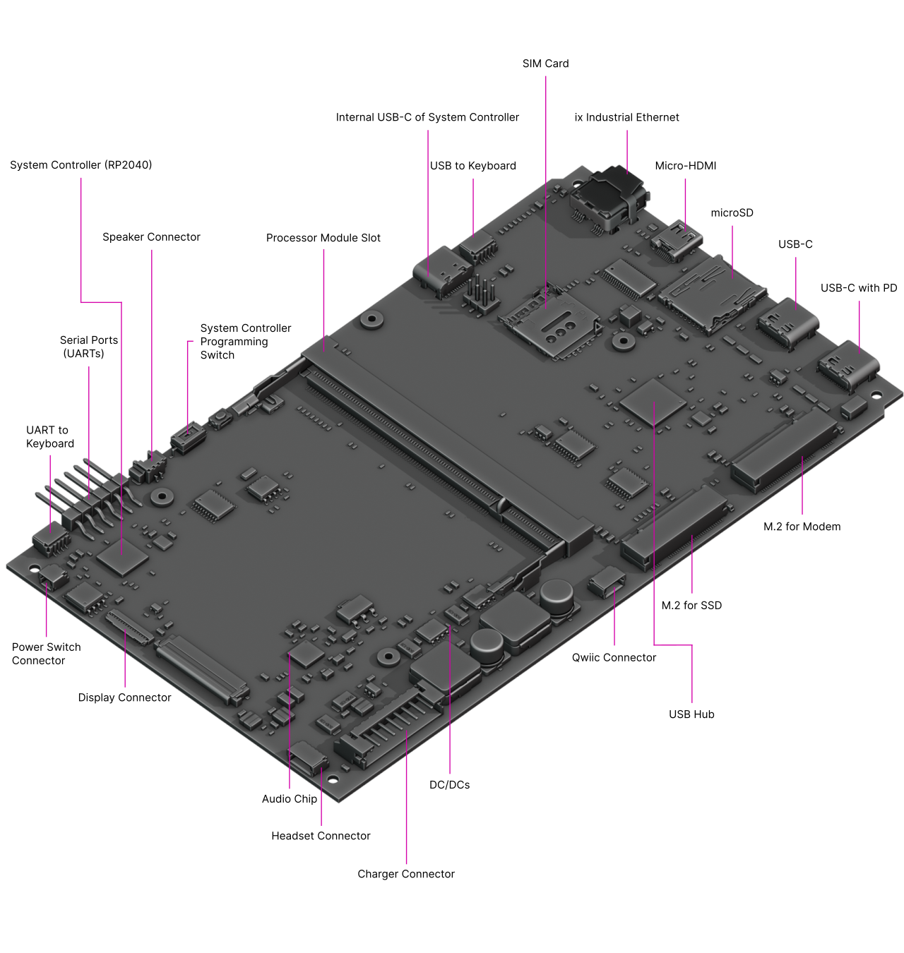
The Motherboard spans the inner width of the device and has outward-facing ports on both sides. It is mounted to the Main Box with two M2x3.5 and two M2x5 countersunk screws. The Motherboard has the following main features:
System controller: based on a RP2040 chip, it implements the high level state machine for the USB-C Power Delivery handling. The lowest levels of the PD protocol are handled in a dedicated chip on the motherboard, the Onsemi FUSB302B, which connects to the first USB-C port’s CC lines. The system controller can also decide to switch that USB-C port’s power line to output instead of input (or Source instead of Sink in PD parlance). This way, you can connect a USB device instead of a charger to the port and have it powered by Pocket Reform.
USB 3.0 hub: The Processor Modules themselves have two USB ports. To provide for a total of four USB ports (two internal and two external), there is a TUSB8041 USB hub chip on the motherboard that provides the extra ports.
Sound chip: A TI TLV320AIC3100 audio DAC (digital-to-analog converter)/amplifier interfaces to the headphone/microphone jack and powers one speaker housed below the main display.
M.2 Key M slot: An NGFF slot (Key M) that can house an NVMe SSD (solid state disk).
M.2 Key B slot: An NGFF slot (Key B) for installing USB-based cards such as cellular modems. We recommend Quectel EM06.
Internal USB-C Port: This port is for flashing the system controller if flashing from the processor module is not possible or in case the system controller is bricked. For this to work, 2 jumpers need to be moved on the header J21 (see chapter “Advanced Topics”).
Internal Qwiic Connector: This 4-pin JST-SH connector offers I2C signals and 3.3V power compatible with Sparkfun’s Qwiic sensors, displays etc. See chapter “Advanced Topics” for more details.
Left Side Ports
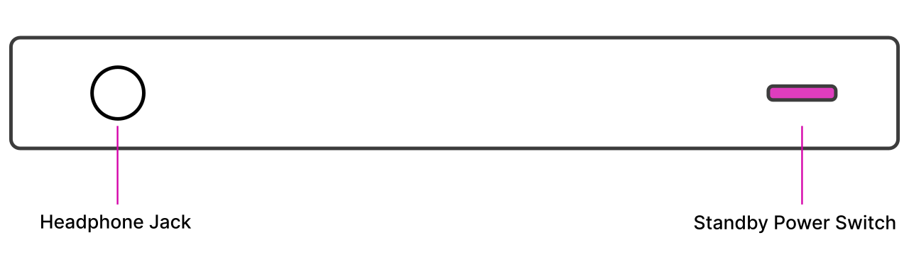
The Left Port Cover exposes the ports of the headset/standby power switch board. The board has a 3.5 mm TRRS connector where you can plug in headphones or a headset with microphone. The board also has a little DIP switch for turning the standby power on/off. The cover is attached with 2 M2 screws.
Right Side Ports
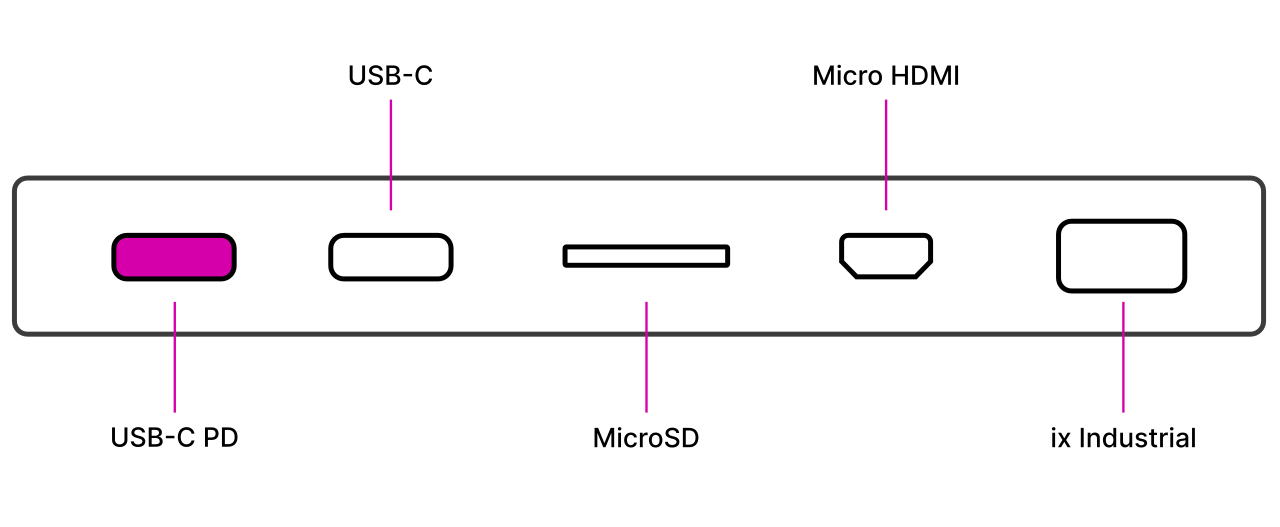
The Right Port Cover is also attached with 2 M2 screws and exposes the 5 ports of the motherboard:
2x USB-C: The leftmost of the USB-C Ports has Power Delivery (PD) functionality which charges the device. Both ports support the connection of USB 3.0/2.0/1.0 devices. There are no alternative modes—it is not possible to connect DisplayPort monitors.
microSD: You can insert a microSD card in this slot. Warning: The system can be booted from microSD cards if a system image is on that card!
Micro-HDMI: Using an adapter, it is possible to connect a HDMI monitor. Note that this is an output port, not an input port.
ix Industrial: This connector supports direct connectivity to wired networks. There are passive adapters for RJ45 Ethernet available.
System Controller
Independent from the main Processor Module, a low-power processor sits on MNT Pocket Reform’s motherboard. The RP2040 is a 32-bit ARM Cortex-M0+ processor that is always on as long as there is battery or wall power present. We call this processor the System Controller.
The System Controller runs a program in a loop that has the following jobs:
Taking care of USB-C Power Delivery
Powering the individual voltage rails of the system on and off
Hard resetting the main processor on demand
Monitoring the voltage of each battery cell
Reporting total current flowing in and out of the batteries
Your main way of communicating with the System Controller is with the keyboard. The keyboard has, aside from its USB connection to the main processor, a second serial (UART) connection/cable to the motherboard’s SYSCTL port. A 57600 bps connection is always established between the keyboard and the System Controller.
It accepts commands in the form of a single letter followed by carriage return (0x0d). A command can also be prefixed with a single argument, a positive integer of up to 4 digits. The most important commands are:
Command |
Function |
|---|---|
1p |
Turn the computer on |
0p |
Turn the computer off |
a |
Get current flowing into/out of batteries in mA |
v |
Get cell voltage statistics |
V |
Get combined battery voltage |
s |
Get System Controller state (a message string) |
g |
Get estimated “fuel gauge” of batteries (percentage) |
To understand the available commands in more detail, you can take a look at the System Controller’s handle_commands() function.
The System Controller is connected to the Processor Module through a SPI interface and through an auxiliary UART. The System Image ships with a kernel module called reform2-lpc which makes battery information available to the OS. The source code for this module is available in the reform2-lpc-driver directory of the MNT Reform repository.
M.2 Socket (Key M)
All Processor Modules feature at least one PCIe controller which is connected to the M.2 socket J10. The standard use for the M.2 Key M port is a NVMe SSD (solid state disk). To install an SSD card, plug it into the socket at an angle and then press down the opposing side into the latch. To remove the card, just pull on the two protruding metal springs of the latch and the card will pop out. An SSD is already installed in Hyper models of MNT Pocket Reform.
The reference clock of the M.2 Key M slot is provided by the Processor Module.
M.2 Socket (Key B)
The shorter M.2 slot with a B Key has USB 2.0 and I2S audio signals. It is intended for cell modems (WWAN) like the Quectel EM06 LTE card. There’s a matching SIM card slot above it on the motherboard. You can set up modem connections using the modem-manager-gui package.
Expansion Port (Qwiic)
On the left side next to the M.2 card slots there’s a port labelled “I2C”. This port (J5) conforms to Sparkfun’s Qwiic standard and features standby 3.3V power as well as I2C clock and data lines which are connected to the RP2040 System Controller. You can extend the System Controller with sensors or display from the Qwiic ecosystem or connect your own custom expansions here and modify the System Controller’s open-source firmware to drive them.
More information about Qwiic: https://www.sparkfun.com/qwiic
Processor Module

The first version of the MNT Pocket Reform ships with an NXP i.MX8M Plus Processor Module. We are constantly developing new modules for Pocket Reform with different features to accommodate individual preferences, like the fast and cost-effective RCM4-BPI module with Amlogic A311D or the latest drop, RCORE with RK3588—a powerful Processor Module that gives you 4x performant ARM Cortex-A76 cores, 4x power-efficient ARM Cortex-A55 cores, and up to 32 GB RAM.
The Processor Module is plugged into motherboard connector U1 which has 200 pins. If you want to learn more about Pocket Reform’s Processor Modules, take a look at the schematics and source KiCad projects in our GitLab repository.
Keyboard
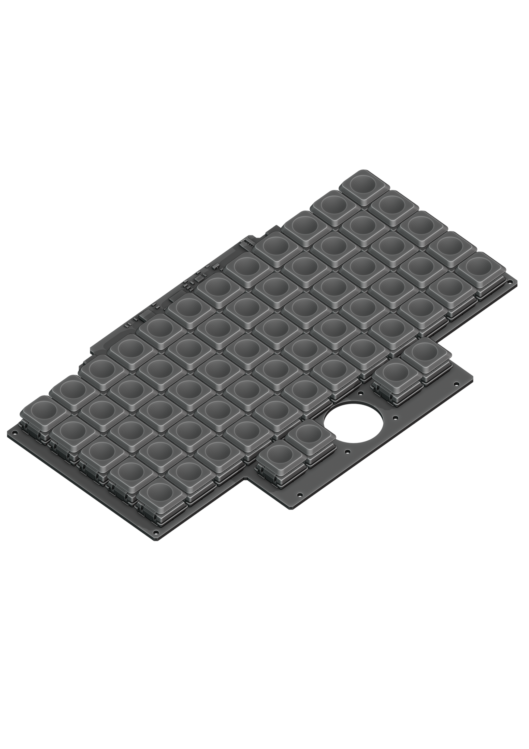
The keyboard is mounted to the top of the Bottom Half with six M2x4 pan head screws. It is powered by an RP2040 32-bit microcontroller. The controller scans the row/column matrix of keyswitches and reports key presses via USB HID (human interface device) to the motherboard. Each switch has a diode to prevent ghosting, so you can press multiple keys at once. The microcontroller runs a firmware based on TinyUSB, which is an open source library for implementing USB devices.
The second role of the keyboard is to serve as a user interface to the System Controller on the motherboard, even when the main SoC is turned off. To make this possible, the keyboard connects via a separate UART cable to the motherboards SYSCTL header.
Backlight
The MNT Pocket Reform keyboard features an RGB backlight. Press the Hyper key and roll the trackball horizontally to change the hue. You can change the brightness level by rolling the trackball vertically. Press Hyper+Shift and roll the ball vertically to adjust saturation.
Replacing a Keycap
MNT Pocket Reform comes with custom MNT Pocket keycaps by FKcaps, which are smaller than regular Choc keycaps so that the keyswitches can be placed closer together than usual. You can pull out individual keycaps with your fingernails—or better, using a keycap puller—and swap them around. Blank replacement keycaps are available at the MNT Research online shop.
Replacing a Keyswitch
Should a keyswitch ever break, you can replace it with any Kailh Choc Switch.
The best way to desolder the switch is a desoldering gun. If you don’t have one, use a soldering iron and solder wick to remove the solder of one pin. Try to pull out the corresponding side of the switch from the top while continuing to heat the pin. Repeat the same for the other pin and go back and forth until you can remove the switch.
OLED Module
The OLED display sits on the OLED Module which is connected to the keyboard through a 4-pin, 1 mm pitch flex cable. The communication protocol is I²C. The module is mounted in the Main Box on top of the keyboard with two M2x4 pan head screws.
If you’re feeling creative and want to customize your OLED with text, images or even animations, we’ve got you covered. Check the MNT Reform source repository and navigate to the reform2-keyboard-fw/kbdgfx-demo directory (this part of MNT Reform is compatible with MNT Pocket Reform). This directory contains example code that serves as a starting point for developing your own custom OLED graphics.
Trackball
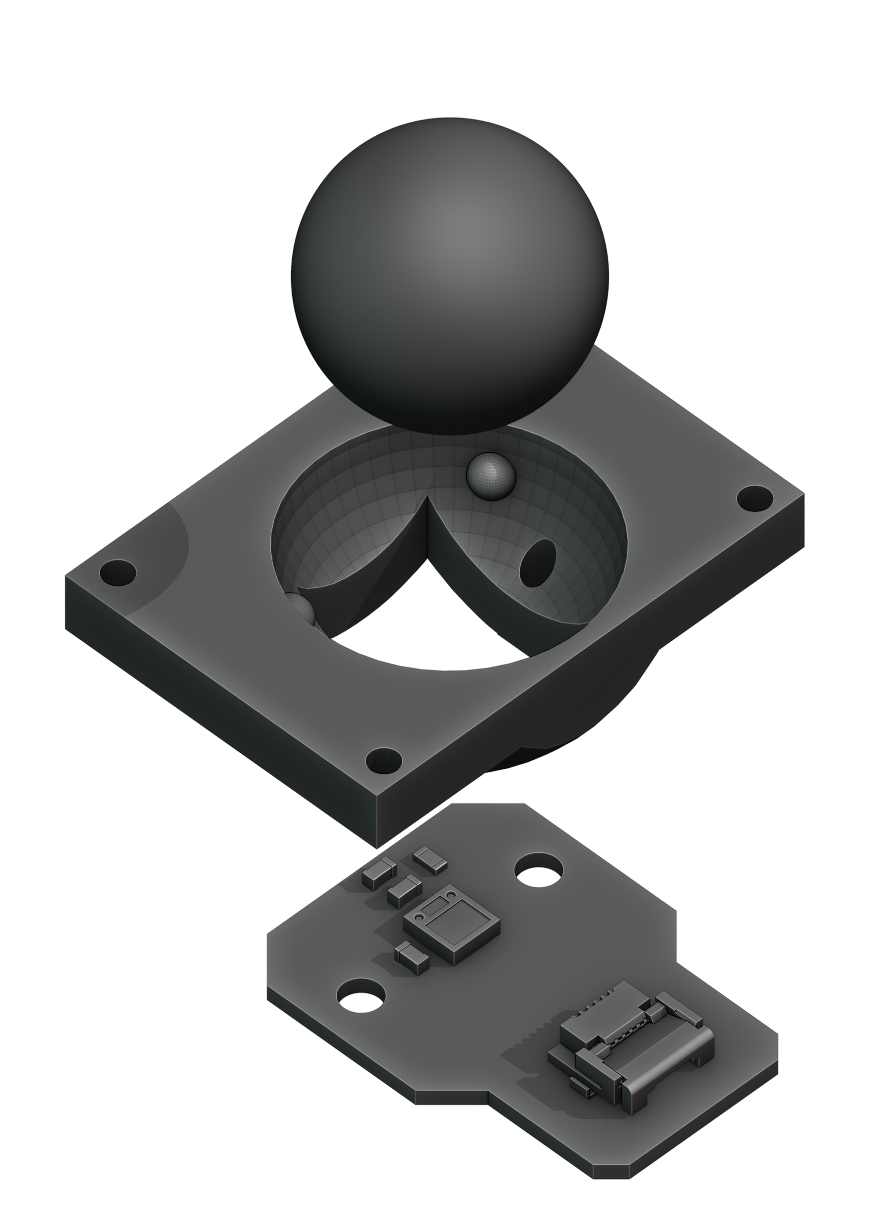
The trackball uses an RP2040 microcontroller to convert X and Y movement coordinates from the PAT9125EL optical sensor that is connected via I²C to the USB HID Mouse protocol. The electronic connection between trackball sensor and controller is made with a 6-pin 0.5mm pitch flex cable.
The trackball has four buttons. These make use of the same Kailh Choc keyswitches as the keyboard. The cup of the trackball is SLA printed.
Trackball Cleaning
From time to time, you should clean dust and debris from the trackball. To do this, unscrew the keyboard frame. Then remove the ball. Clean the inside of the cup with a soft cloth. Don’t use detergents as these can dissolve the cup’s material.
Headset Board
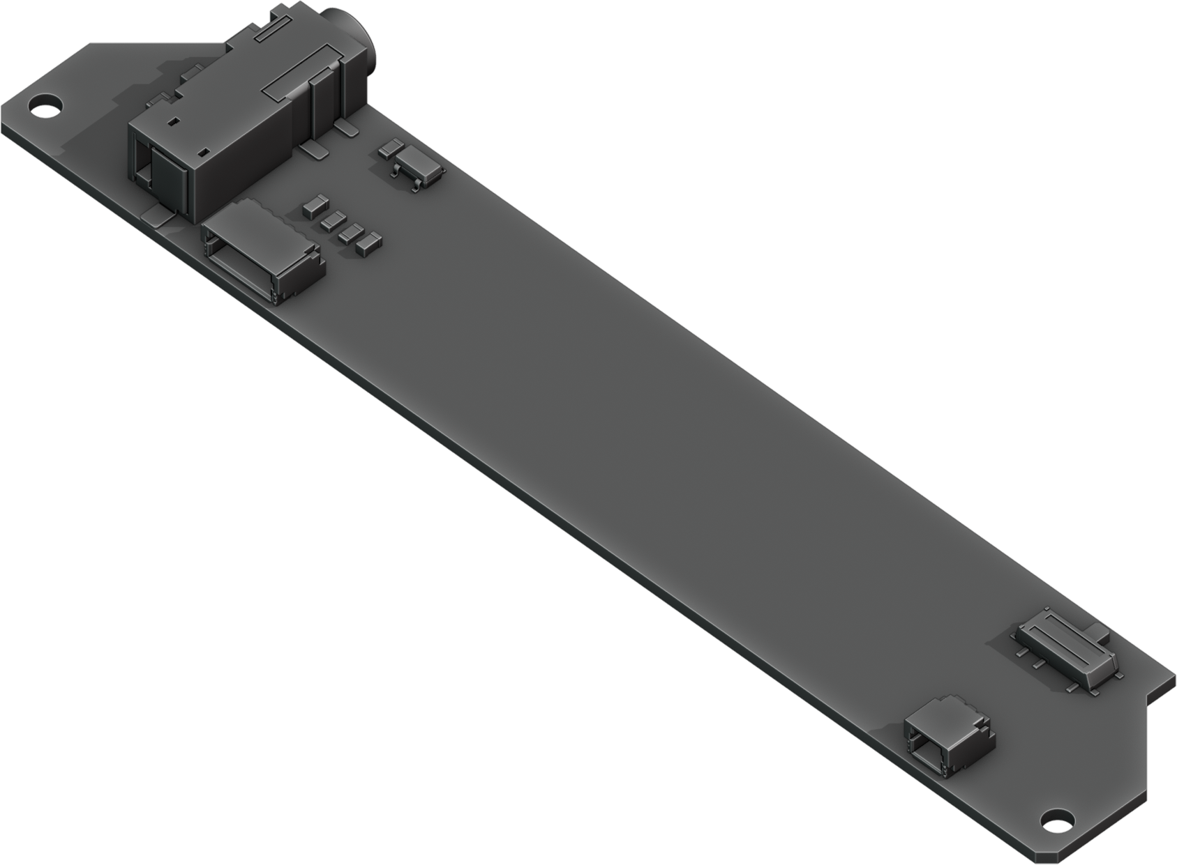
The headset board is a PCB that has the following features:
Headset Jack
Standby Power Switch
Audio Connector to Motherboard
Power Connector to Motherboard
Depending on your processor module, this board can have additional features like a Wi-Fi/Bluetooth card slot.
Battery Cells
MNT Pocket Reform has two identical battery cells (Li-ion pouches), referred to as the Left and Right cells. The cells are held in place with two SLA printed battery holders each.
Compatible Battery Cells
The following table lists compatible Li-ion cells. It is not recommended to mix cells of different capacities, as the lowest capacity cell will dictate the lowest safe point of discharge.
Brand |
Model |
Capacity |
|---|---|---|
EREMIT |
606090 |
3.7V 4000mAh LiPo |
Charger Board
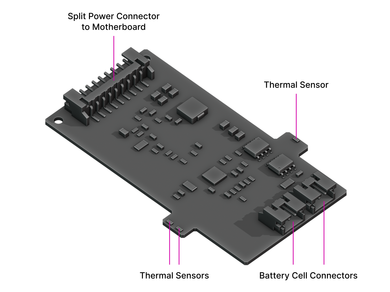
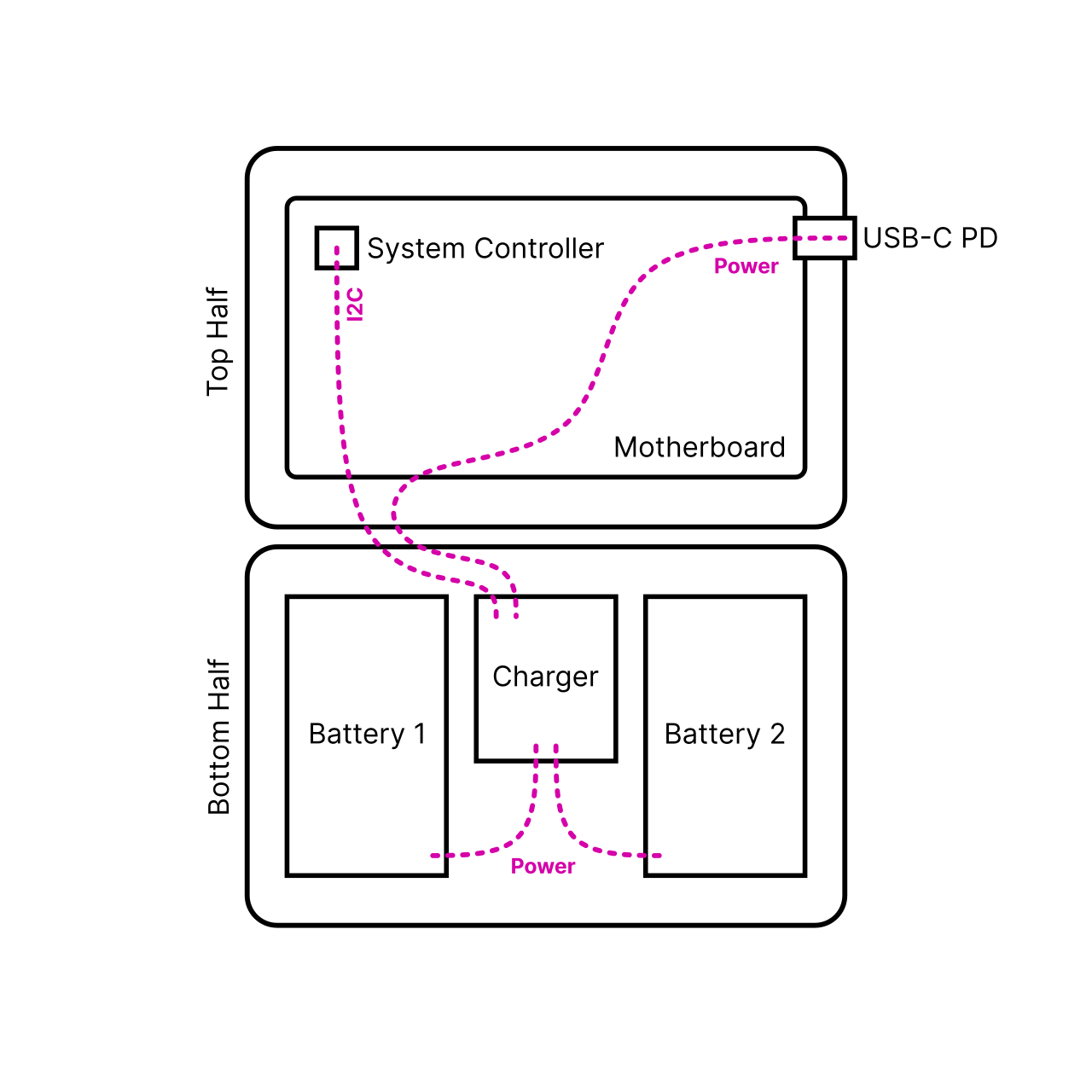
Underneath the keyboard reside two LiPo battery cells with 606090 form factor. In their middle: the charger board. This little PCB mainly contains two chips: one is a fuel gauge with battery protection (MAX17320G20+), and one is the actual charger, the MPS MP2650. These chips are decoupled from the motherboard to allow for future flexibility in terms of battery architectures and chemistries, and to allow both the motherboard and the charger to be reused in other contexts.
The interface between charger and mainboard is a 9-pin JST PH connector with the following pinout:
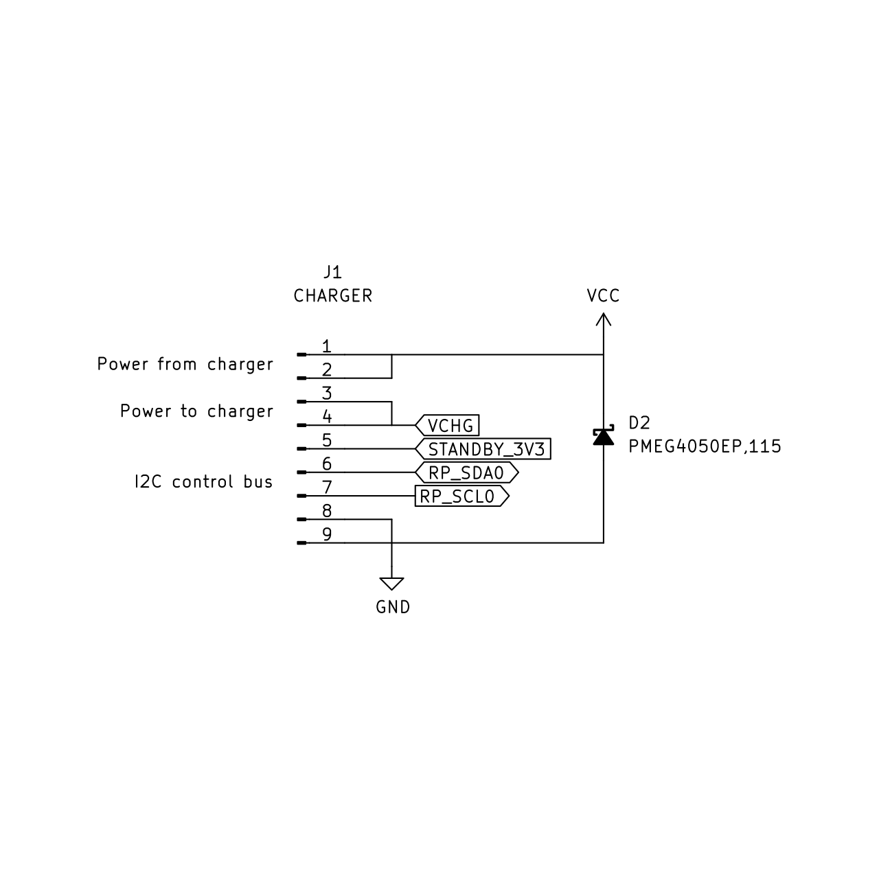
“Raw power” from an external source—in this case, from a USB-PD charger—enters the charging board, and system power, sourced and regulated by the MPS from either the batteries or the external input, comes out and goes back to the motherboard. The I2C bus is for communication with the charger and protector chips.
The charger has 2x 2-pin JST-PH battery cell connectors. It also has 2 small “arms” on each side with temperature sensing resistors that touch the battery cells.
Compatible Displays
MNT Pocket Reform was designed to be compatible with a number of 7 inch (diagonal) 1200x1920 pixel MIPI-DSI displays. We tested the following display models successfully:
Brand |
Model |
|---|---|
JDI |
LT070ME05000 |
Wisecoco |
TOP070F01A (with adapter) |
Please note that the display is physically rotated by 90 degrees. The console and desktops of the standard System Image are configured for this, but if you install an alternative desktop environment, you’ll have to adjust the display settings to compensate for this rotation.