Hardware
Case Parts
The case consists of the following 5 parts. All parts except the Bottom Plate are milled from sand-blasted and anodized 6061 aluminum.
Main Box: the chassis of MNT Reform. All PCBs (printed circuit boards) are attached to it via screws: The keyboard from the top and motherboard, trackball/trackpad, and battery boards from the bottom. The lower half of the hinges and the system controller OLED PCB are mounted from the top as well.
Keyboard Frame: a thin rectangle that covers the sides of the keyboard and the system controller OLED
Screen Back: houses the display and upper half of hinges
Screen Front: houses speakers and providing display bezel
Bottom Plate: the clear acrylic plate that closes the laptop from the bottom
For easy (dis)assembly, Reform uses M2 screws with Phillips-head everywhere—with one exception: M4x5 on the top half of the hinges.
Main Box
The Main Box houses most of the electronics:
Motherboard, exposing ports through openings on the left and right
Two LiFePO4 battery packs, connecting to the motherboard via Molex PicoLock cables
Keyboard, connecting to the motherboard via two JST-PH cables
OLED display, connecting to the keyboard via a 4-pin 1mm pitch flex cable
Trackball or Trackpad, connecting to the motherboard via one JST-PH cable
The Main Box features four neodymium bar magnets inserted into slots below the front edge. These match with their counterparts in the Screen Front.
Keyboard Frame
The Keyboard Frame is inserted into the Main Box. It has four tabs on the front that must be inserted first. The frame is mounted with six black M2x5 countersunk screws.
Screen Back
The eDP display panel rests in the Screen Back. The left and right hinges are mounted in the bottom left and right corners with three M4x5 countersunk screws each. Note that the hinge labeled “SMS-ZZ-219-L” goes on the right side, and the hinge labeled “SMS-ZZ-219-R” goes on the left side. The other half of each hinge is mounted to the Main Box with four M2x6 countersunk screws.
Four neodymium magnets are mounted along the top edge of the Screen Back. These, together with their counterparts in the Main Box, hold the laptop shut when closed.
The stereo speakers are mounted below the display and secured with the speaker holders. Each holder is mounted with two black M2x5 countersunk screws. Both speaker and display cable are fed through a cutout in the hinge and into the Main Box.
Screen Front
This part serves as a bezel for the display. It is mounted with seven black M2x5 countersunk screws to the Screen Back.
Bottom Plate
The Bottom Plate closes the Main Box from the bottom with ten M2x6 countersunk screws.
Port Covers
The Port Covers are two pieces of powder coated steel that cover the side openings of the Main Box (mounted with two black M2x5 screws each). You can exchange these to fit a future motherboard or an expansion that requires a different port layout.
Motherboard
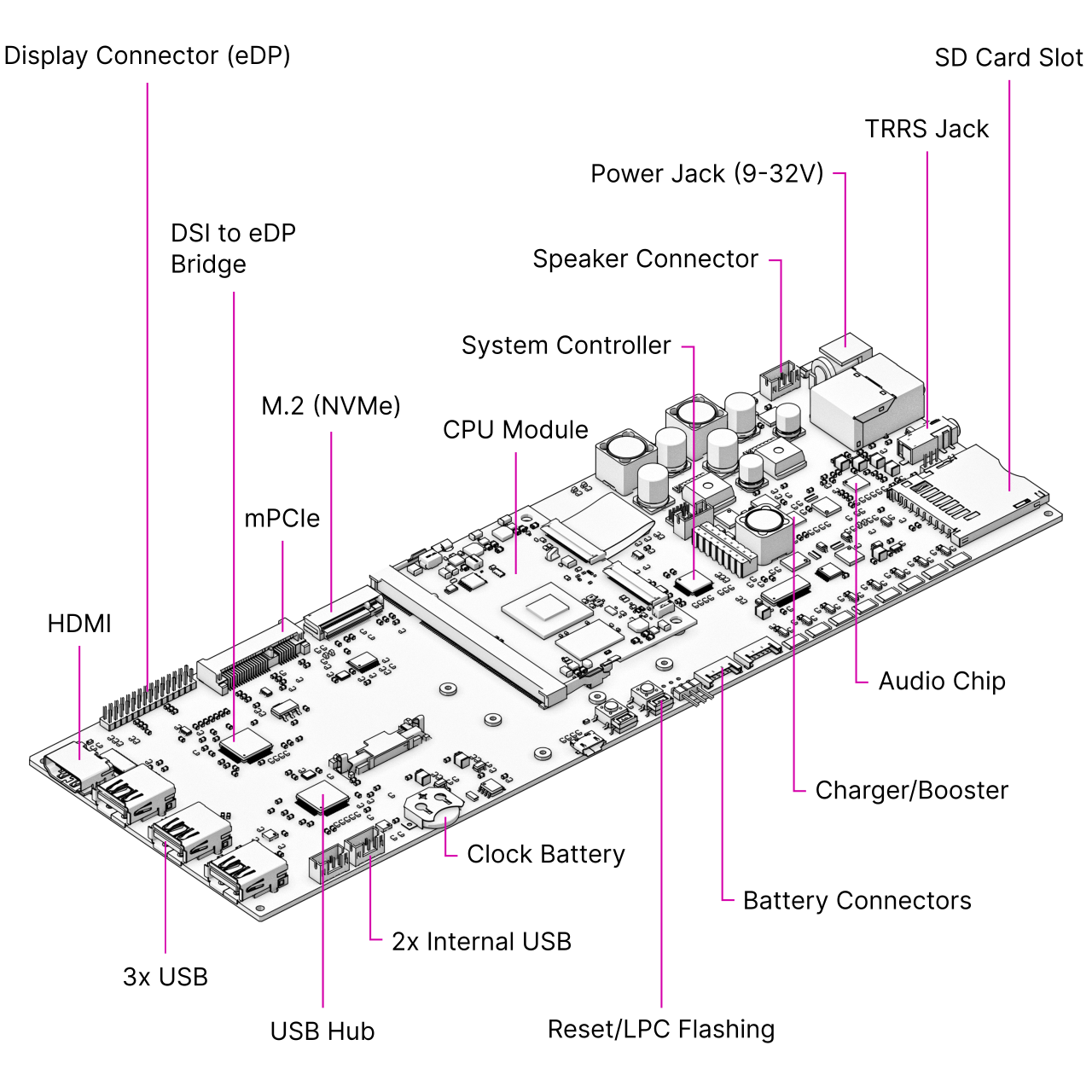
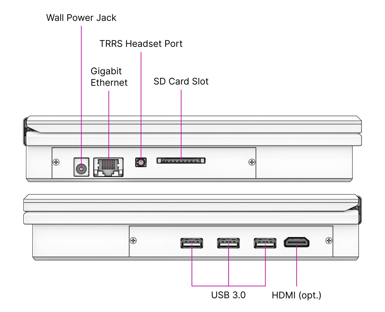
The Motherboard spans the inner width of the device and has outward-facing ports on both sides. It is mounted to the Main Box with four M2x4 pan head screws. The Motherboard has the following main features:
Power system: based on the LTC4020 buck/boost converter, it regulates charging of the LiFePO4 batteries and seamlessly switches between wall and battery power.
System controller: coupled to the power system, an NXP LPC11U24 Cortex-M0 MCU controls an analog monitor chip for the eight battery cells as well as the charger. It is connected to the Processor Module via SPI, and has GPIO lines to the main power rail switchers in the system. It has a UART (SYSCTL) that the keyboard can talk to directly for issuing power on/off commands and battery status queries.
DSI to eDP bridge: The SN65DSI86 chip converts the MIPI-DSI output from the Processor Module to an embedded DisplayPort (eDP) signal that the display panel can understand. Some Processor Modules don’t make use of this chip, because they can output eDP directly (like the LS1028A) or use an internal HDMI to eDP adapter instead. Please refer to your Processor Module’s manual for the details.
USB 3.0 hub: The Processor Modules themselves have two USB ports. To provide for a total of five USB ports (two internal and three external), there is a TUSB8041 USB hub chip on the motherboard that provides the extra ports. USB load switches on each external port protect the system from too much current draw.
Sound chip: A Wolfson/Cirrus WM8960 audio DAC (digital-to-analog converter)/amplifier interfaces to the headphone/microphone jack and powers two speakers housed below the main display.
mPCIe slot: An mPCIe connector that you can use for expansions like a Wi-Fi card or for an NVMe SSD using an M.2 adapter.
M.2 slot: An NGFF slot (Key M) that can either house an NVMe SSD (solid state disk), or with the LS1028A module, a SATA SSD. With some other Processor Modules, this port is inactive (refer to the Processor Module’s manual).
Revised Versions
At the time of writing, 3.0 is the latest motherboard version. It is a revised version of the 2.5 Reform motherboard, and it is compatible with all our Processor Modules.
Changes in Version 3.0:
Replaced Barrel jack with USB-C power delivery input (via firmwareless TPS25730)
Added USB-UART chip that offers CPU debug consoles and system controller debug UART on that same USB-C port (CY7C65215)
Replaced old 5V and 3.3V main buck converters with modern ones from Reform Next (LM62460)
Added direct power input header for custom power solutions like solar
Bumped NVMe SSD slot from 1x to 4x PCIe lanes (for RK3588)
Updated PCIe reference clocking chip for PCIe Gen 3 support
Fixed headphone jack detection (resistor update)
Fixed/limited LTC4020 charge current overdraw (resistor R8 replaced with 7.15k)
Redid 5V power rails for USB for higher current and increased capacitance to handle more USB device power draw
Upgraded USB hub from TUSB8040 to TUSB8041
Removed unnecessary internal 5V and 3.3V power switches
Added QwiiC port for I2C expansion via LPC (for example for sensors)
Added QwiiC port for I2C expansion via CPU
Replaced SD card slot model
Updated 1.8V LDO for more modern one
Removed some unnecessary/unused resistors, signals, and headers
Improved/redrew some routing and ground fills
Replaced 3.3V LDO for USB-UART with buck converter
Changes in Version 2.5:
Lowered headphone lowcut filter for improved bass response
Replaced Micro-USB with USB-C as the LPC flashing connector
Lowered power LED brightness
Fixed current leak through balancing circuit that could bypass missing cells
Fixed main buck converter enable behavior under low voltage condition
Fixed charger control circuit that previously required a factory resistor bodge
System Controller
Independent from the main Processor Module, a low-power processor sits on MNT Reform’s motherboard. The NXP LPC11U24 is a 32-bit ARM Cortex-M0 processor that uses very little power and is always on as long as there is battery or wall power present. We call this processor the System Controller.
The System Controller runs a program in an endless loop that has the following jobs:
Powering the individual voltage rails of the system on and off
Hard resetting the main processor on demand
Monitoring the voltage of each battery cell
Balancing battery cells. If a cell is overvolted, charging is halted and the overvolted cells are discharged until they are back to a nominal voltage
Turning off the system if battery cells are undervolted
Reporting total current flowing in and out of the batteries
Turning charge current on or off
Your main way of communicating with the System Controller is with the Keyboard. The Keyboard has, aside from its USB connection to the main processor, a second serial (UART) connection/cable to the motherboard’s SYSCTL port. A 57600 bps connection is always established between the Keyboard and the System Controller.
It accepts commands in the form of a single letter followed by carriage return (0x0d). A command can also be prefixed with a single argument, a positive integer of up to 4 digits. The most important commands are:
Command |
Function |
|---|---|
1p |
Turn the computer on |
0p |
Turn the computer off |
a |
Get current flowing into/out of batteries in mA |
v |
Get cell voltage statistics |
V |
Get combined battery voltage |
s |
Get System Controller state (a message string) |
g |
Get estimated “fuel gauge” of batteries (percentage) |
The individual cell voltages are measured by the Battery Monitor LTC6803IG-4#PBF and reported via SPI to the System Controller. The total voltage and current are measured by the INA260 chip and reported via I²C.
To understand the available commands in more detail, you can take a look at the System Controller’s handle_commands() function.
The System Controller is connected to the Processor Module through a SPI interface and through an auxiliary UART. The System Image ships with a kernel module called reform2-lpc which makes battery information available to the OS. The source code for this module is available in the reform2-lpc-driver directory of the Reform repository.
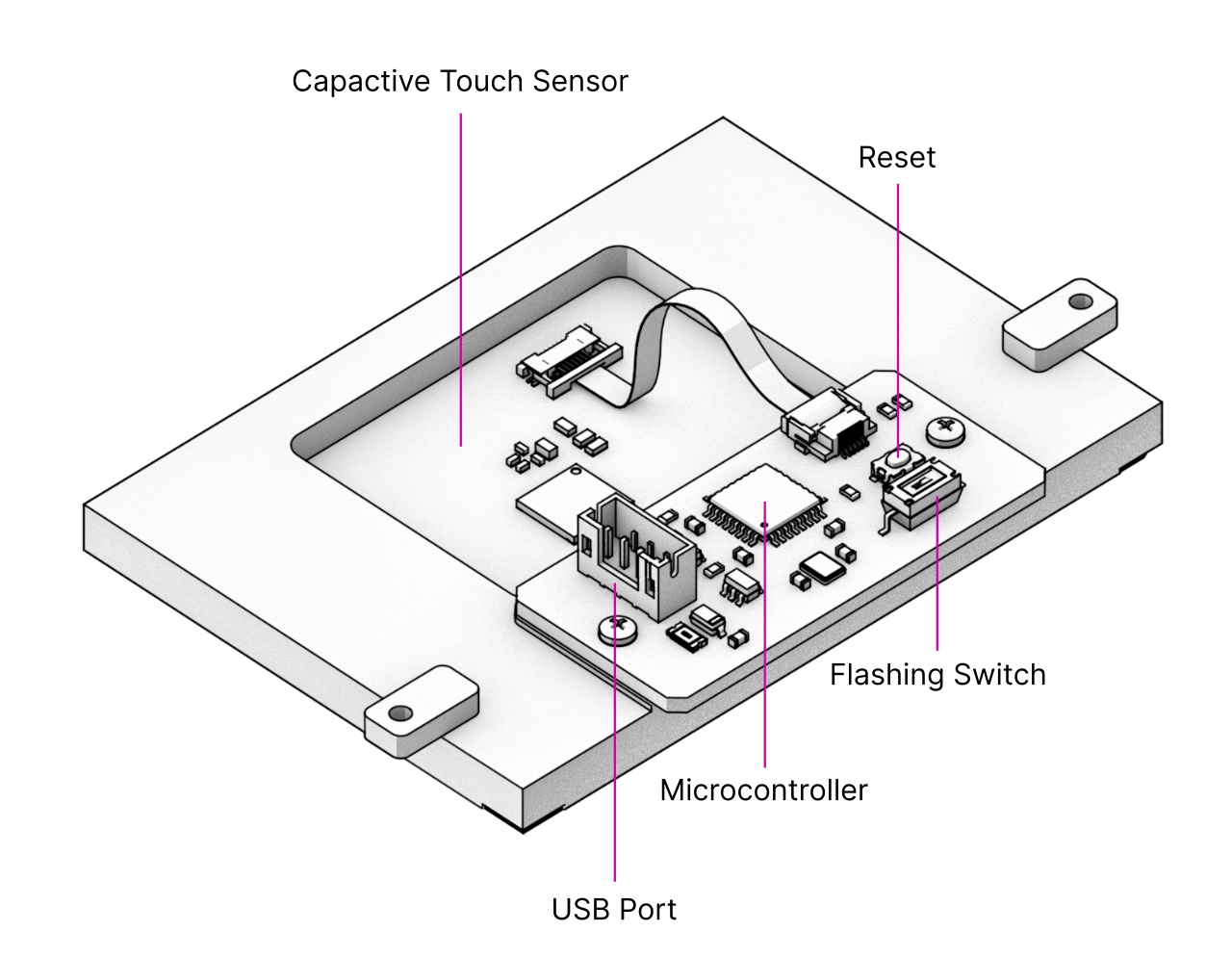
Flashing the Firmware
To update (flash) the firmware of the System Controller, you need another computer and a USB-C cable (or, if you have a motherboard older than version 2.5, a Micro-USB cable).
You can find the source code of the firmware and a script that guides you through the flashing process in MNT Reform’s source folder reform2-lpc-fw.
On your other computer, execute the following commands:
git clone https://source.mnt.re/reform/reform
cd reform/reform2-lpc-fw
./download-fw.sh 30_R1
sudo ./flash.sh
If you have an older motherboard version, substitute 30_R1 above for the appropriate version number. You can see all version numbers by running ./download-fw.sh without any arguments.
The flash.sh script will interactively guide you through the necessary steps. These are:
Open MNT Reform’s lid and remove the batteries.
Connect the charger. Be very careful to avoid shorts from this point on.
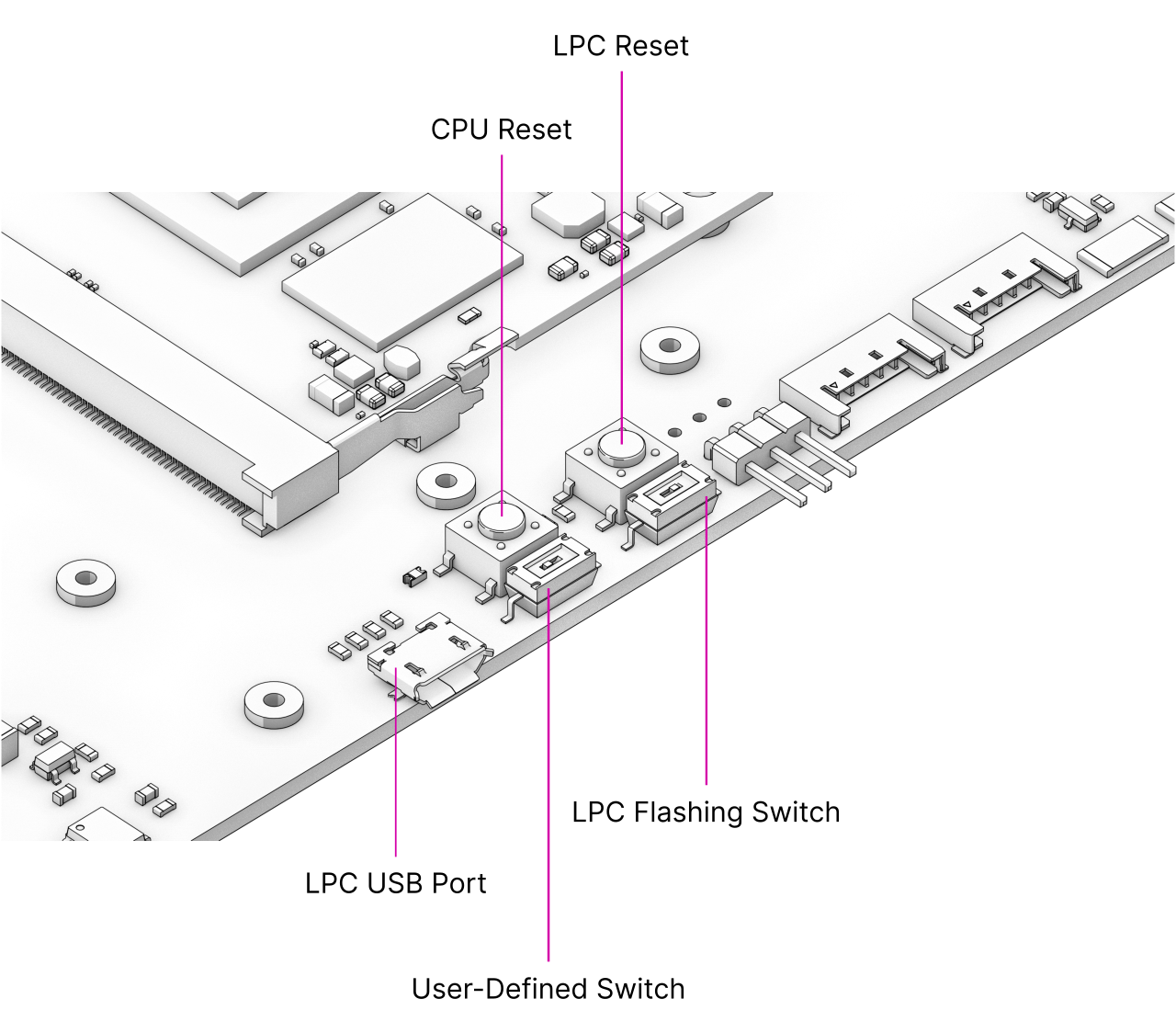
Set DIP switch LPCPROG (LPC Flashing Switch) on MNT Reform’s motherboard to “ON”.
Press button LPCRESET.
Connect USB-C (or Micro-USB) cable between MNT Reform’s motherboard and your other computer.
System Controller’s memory appears as a virtual flash drive. The
flash.shscript will recognize it and copy thefirmware.binto this virtual drive.Unplug the USB-C or Micro-USB cable.
Set DIP switch LPCPROG (LPC Flashing Switch) to “OFF” (labelled “1” on the switch).
Press button LPCRESET.
Disconnect the charger and reassemble your MNT Reform.
Alternatively, you can build the firmware yourself. Please follow the instructions in the README.md file to do so.
Expansion Port
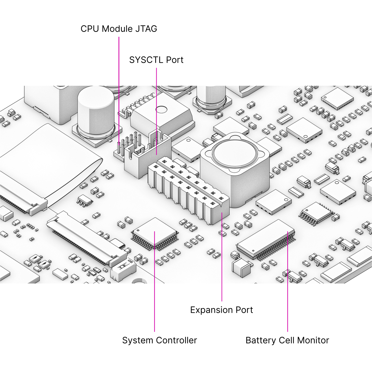
The Expansion Port U18, labeled “Hack the Planet” is meant for advanced users that want to connect sensors or other peripherals to MNT Reform’s system controller. Please note that changing the system controller’s program can disrupt the battery charging control loop, potentially causing over- or undercharged cells, resulting in physical damage and/or injury. Experiment with the system controller only if you know exactly what you’re doing and at your own risk.
The Expansion Port features an SPI interface, two analog-digital converters, a UART, JTAG and 3.3V Power. All non-power pins can alternatively be used as GPIOs.
The following LPC11U24 pins are available at the port:
Pin |
Function |
Pin |
Function |
|---|---|---|---|
16 |
GND |
15 |
3.3V |
14 |
MOSI1a |
13 |
USBCON# |
12 |
RXDa |
11 |
TXDa |
10 |
AD7 |
9 |
SCLKa |
8 |
SWDIO |
7 |
AD5 |
6 |
TDO |
5 |
TRST# |
4 |
TDI |
3 |
TMS |
2 |
MISO1a |
1 |
SCK0b |
Refer to the motherboard schematic’s Power section and the NXP LPC11U24 reference manual for further details.
mPCIe Socket
All Processor Modules feature at least one PCIe controller which is connected to the mPCIe socket U11. The standard use for the mPCIe port is a WiFi card or an NVMe SSD (with M.2 adapter). To install a card, plug it into the socket at an angle and then press down the opposing side into the latch. To remove the card, just pull on the two protruding metal springs of the latch and the card will pop out.
The reference clock of the mPCIe slot is provided by the Processor Module.
M.2 Socket (Key M)
Some Processor Modules, such as the original i.MX8M module and the RCORE with RK3588, feature a second PCIe controller—or in the case of LS1028A, a SATA controller—which is connected to the M.2 socket (J10). The standard use for the port is to install an M.2 NVMe solid state drive. Plug the SSD disk into the socket and fix it with an M2 screw to one of the three mounting holes that corresponds to the module’s size.
The reference clock for the port is generated by U23 on the motherboard.
Processor Module
When the first edition of this handbook was released, we had only one Processor Module to offer. Now, nearly four years later, there are several of them, each with different features to accommodate individual preferences. We are constantly developing new modules for Reform, the latest drop being RCORE with RK3588—a powerful Processor Module that gives you 4x performant ARM Cortex-A76 cores, 4x power-efficient ARM Cortex-A55 cores, and up to 32 GB RAM.
The Processor Module is plugged into motherboard connector U1 which has 200 pins. If you want to learn more about Reform’s Processor Modules, take a look at the schematics and source KiCad projects in our GitLab repository.
If you want to develop your own Processor Module, visit https://source.mnt.re/reform/reform-som-template for a KiCad template and more technical information.
Display Connector
The default display in MNT Reform conforms to the eDP (embedded DisplayPort) standard. Some Processor Modules, such as i.MX8M and RCM4, output a MIPI-DSI signal on its flex connector that is fed into the J24 connector on the motherboard using the 30 pin, 0.5mm pitch flex cable. The SN65DSI86 chip on the motherboard converts the MIPI-DSI signal to eDP. If you use a different Processor Module that outputs eDP directly, the J24 connection is skipped. Refer to the manual of your module instead.
Heatsink
The heatsink is a piece of milled aluminum that connects to the silicon die of the main SoC on the Processor Module, with a thermal pad applied on the die. The heatsink is fixed to the motherboard by four M2x12 screws. The screws are supported by four metal or plastic spacers.
Keyboard
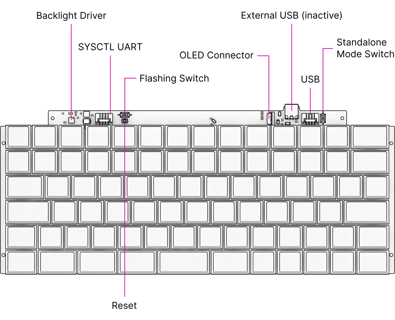
The keyboard is mounted to the top of the Main Box with six M2x4 pan head screws. It is powered by an RP2040 microcontroller. The controller scans the row/column matrix of keyswitches and reports key presses via USB HID (human interface device) to the motherboard. Each switch has a diode to prevent ghosting, so you can press multiple keys at once. The microcontroller runs a firmware based on pico-sdk and tinyusb which is an open source library for implementing USB input devices.
The second role of the keyboard is to serve as a user interface to the LPC system controller on the motherboard, even when the main SoC is turned off. To make this possible, the keyboard connects via a separate UART cable to the motherboard’s SYSCTL header (J23).
The keyboard can also be taken out of the laptop and used as a standalone USB-C device. To enable this function, turn on the STANDALONE switch near the top right corner. When using the keyboard in the laptop, this switch has to be turned off.
Keyboard Firmware
You can update the firmware of the keyboard on MNT Reform itself, but make sure to read this section in full to avoid ending up in a situation where you have to disassemble the laptop.
You’ll need an external USB keyboard to finish the process, as your laptop’s keyboard will stop responding after entering firmware update mode. Otherwise, you can only recover from this mode by opening the laptop and pressing the keyboard’s reset button or disconnecting and reconnecting the battery or keyboard cables.
To be able to flash the firmware to the keyboard, its microcontroller has to be in this special programming mode. Since the 3.0 revision of the Keyboard, you can put it in programming mode by pressing the Circle key followed by the X key.
For keyboard 4.0 (with RGB backlight), execute these commands:
git clone https://source.mnt.re/reform/reform
cd reform/reform2-keyboard4-fw
./download-fw.sh laptop-us
sudo ./flash.sh
Substitute laptop-us with laptop-intl if you have a non-US keyboard layout.
For older keyboard versions (white backlight):
git clone https://source.mnt.re/reform/reform
cd reform/reform2-keyboard-fw
./download-fw.sh 3_US # or 3 if you have a
                      # non-US keyboard
                      # or 2 if you have an
                      # older pre-V3 keyboard
sudo ./flash.sh
You can find MNT Reform keyboard firmware sources for the current version with RGB backlight in the source folder reform2-keyboard4-fw.
MNT Reform keyboard firmware sources for older versions of the keyboard are in the source folder reform2-keyboard-fw.
Backlight
Most keys have a light emitting diode (LED) to illuminate the transparent part of the keycaps, making the laser engraved letters visible in darkness. You can control the backlight’s brightness via Circle followed by F1 or F2, or use the OLED menu. To change the backlight’s color on MNT Reforms with keyboard 4.0, you can use F3/F4 for hue and F5/F6 for saturation control while the OLED menu is open.
Replacing a Keycap
MNT Reform comes with custom MBK Choc Glow keycaps by FKcaps, but you can use any keycaps compatible with Kailh Choc keyswitches. You can pull out individual keycaps with your fingernails—or better, using a keycap puller—and swap them around.
Replacing a Keyswitch
Should a keyswitch ever break, you can replace it with Kailh Choc Brown (CPG135001D02) or Kailh Choc White (CPG135001D03).
The best way to desolder the switch is a desoldering gun. If you don’t have one, use a soldering iron and solder wick to remove the solder of one pin. Try to pull out the corresponding side of the switch from the top while continuing to heat the pin. Repeat the same for the other pin and go back and forth until you can remove the switch.
OLED Module
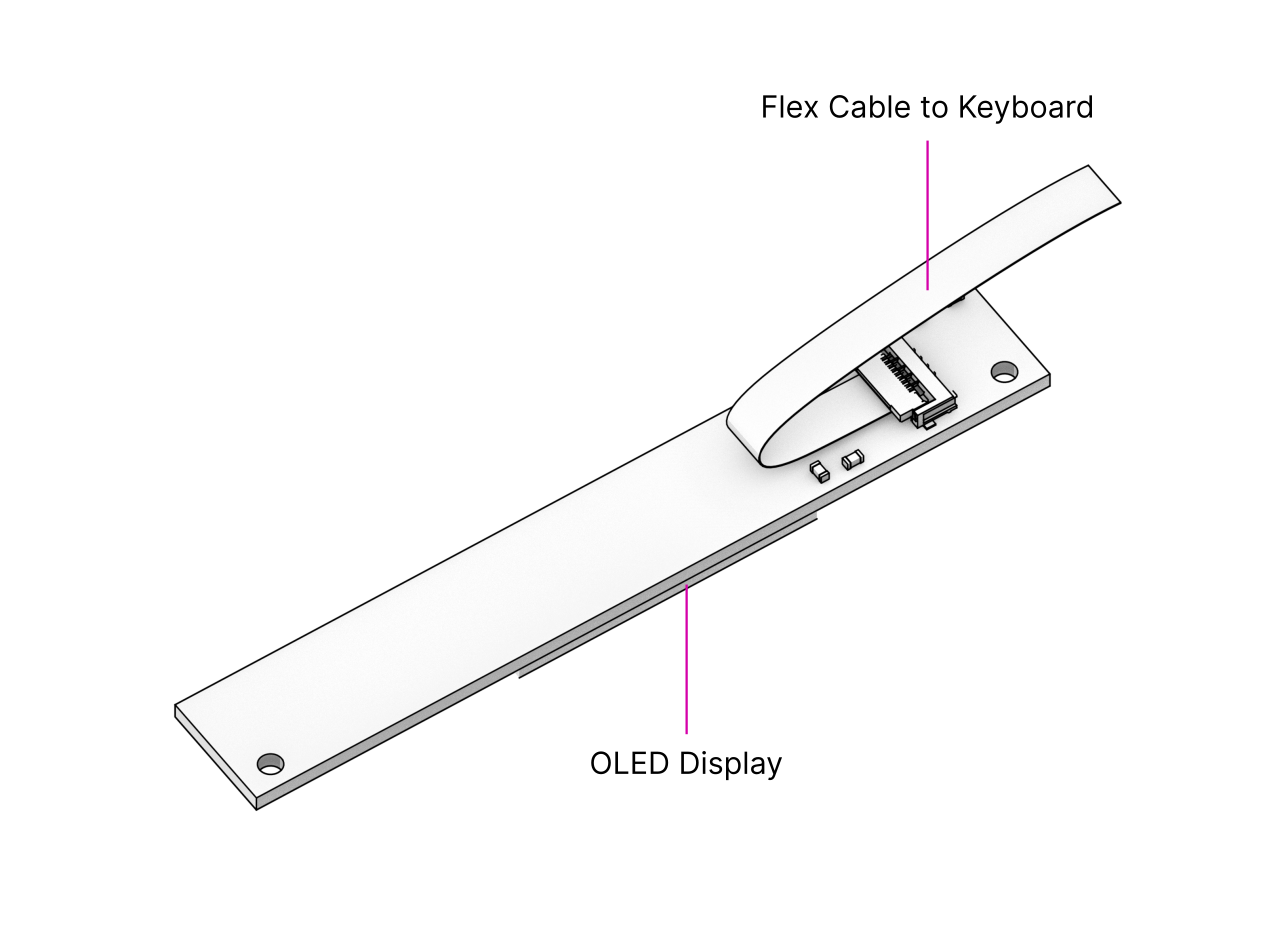
The OLED display sits on the OLED Module which is connected to the keyboard through a 4-pin, 1mm pitch flex cable. The communication protocol is I²C. The module is mounted in the Main Box on top of the keyboard with two M2x4 pan head screws.
If you’re feeling creative and want to customize your OLED with text, images or even animations, we’ve got you covered. Check the MNT Reform source repository and navigate to the reform2-keyboard-fw/kbdgfx-demo directory. This directory contains example code that serves as a starting point for developing your own custom OLED graphics.
Trackball
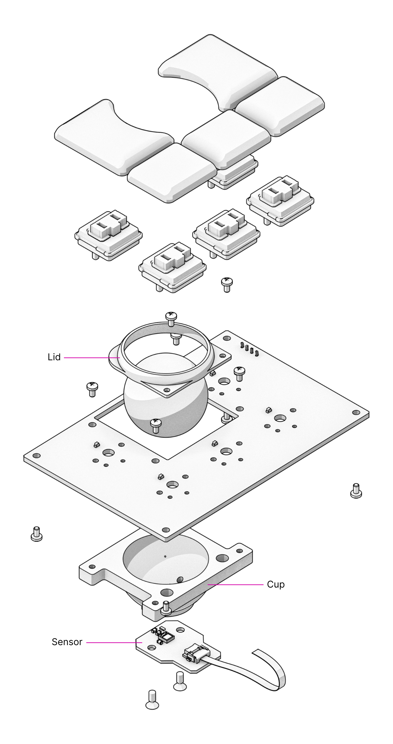
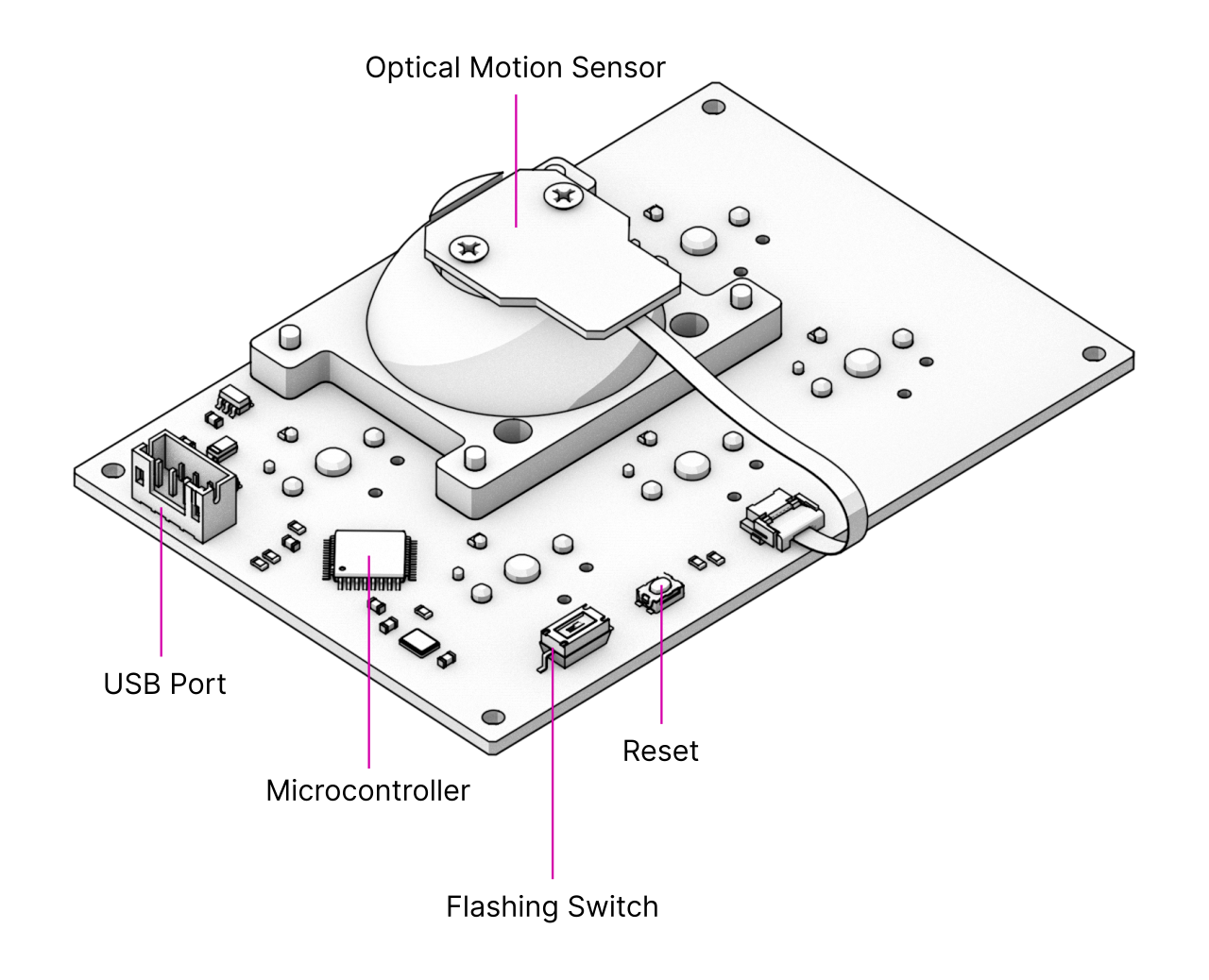
The trackball uses an RP2040 microcontroller to convert X and Y movement coordinates from the PAT9125EL optical sensor that is connected via I²C to the USB HID Mouse protocol. The electronic connection between trackball sensor and controller is made with a 6-pin 0.5mm pitch flex cable.
The trackball has five buttons. These make use of the same keyswitches as the keyboard: Kailh Choc Brown (CPG135001D02). The button caps are 3D printed using SLA resin technology. If you want to substitute your own replacements, you can find the STL files for the caps in the MNT Reform source repository. The cup and lid of the trackball are 3D printed using the same method.
Trackball Cleaning
From time to time, you should clean dust and debris from the trackball. To do this, carefully lift off the left and right buttons. Then, unscrew the two screws holding the trackball’s lid and remove the ball. Clean the inside of the cup with a soft cloth. Don’t use detergents as these can dissolve the cup’s material.
Trackball Firmware
You can find the trackball firmware in the source folder reform2-trackball2-fw, except if you have an older version of the trackball that uses an ATmega32U2 controller instead of a RP2040. The older versions firmware is in the reform2-trackball-fw directory. Please refer to its README.md file for building and flashing information.
You can download and flash the firmware as follows:
git clone https://source.mnt.re/reform/reform
cd reform/reform2-trackball2-fw
./download-fw.sh
sudo ./flash.sh
If you want to modify the behavior of the trackball, refer to the README.md file in the firmware directory.
Trackpad
The trackpad integrates an Azoteq TPS65-201 capacitive sensor which reports coordinates to the microcontroller via the SPI protocol.
Trackpad Firmware
You can find the trackpad firmware in the source folder reform2-trackpad-fw.
Same as the keyboard, the trackpad firmware is based on the LUFA USB device library and implements a USB HID Mouse.
To update the firmware, the MCU has to be in bootloader USB mode. If you have a recent enough trackpad firmware, the flashing script can put it in this mode directly. If this doesn’t work, you have to open your MNT Reform and toggle the programming DIP switch SW7 on the trackpad to “ON” and press the reset button SW6. The trackpad will reappear as an “Atmel DFU bootloader USB” device. You can then download and flash new firmware by executing:
git clone https://source.mnt.re/reform/reform
cd reform/reform2-trackpad-fw
./download-fw.sh
sudo ./flash.sh
If you want to modify the behavior of the trackpad, refer to the README.md file in the firmware directory.
Exchanging Trackball and Trackpad
You can swap the Trackball for the Trackpad module and vice versa. To do this, first disconnect the wall power and flip MNT Reform on its back. Unscrew the Bottom Plate and remove all battery cells. Unplug the side of the internal USB cable that is connected to the installed module. Then, unscrew the module’s case mounting screws (four M2x4 pan head screws for the Trackball, two M2x4 pan head screws for the Trackpad) and pull out the module.
Reverse the process to install the new input device. The Trackball is inserted so that its four mounting holes line up with four matching holes in the Main Box. The Trackpad slides into a slot in the Main Box with one end first (the end without mounting tabs) and is then mounted to the Main Box with two screws that go through the tabs on the other end. After mounting the desired module, reconnect the internal USB cable to it.
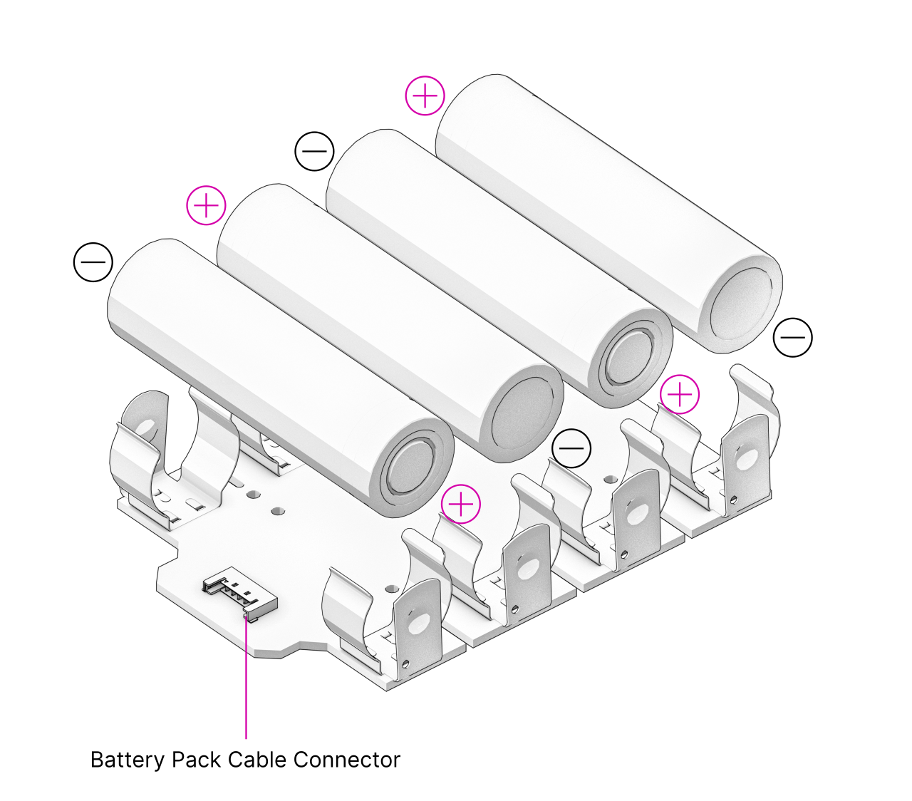
Battery Packs
MNT Reform has two identical battery packs, referred to as the Left and Right packs. Each pack holds four 18650 LiFePO4 cells (3.2V). The two packs are mounted to the Main Box with four M2x4 pan head screws for each battery pack. You may be tempted to try cells of other chemistries like Li-Ion or NiMH, but never do this, as these are incompatible.
Only use LiFePO4 cells with MNT Reform!
When inserting battery cells, make sure that the positive and negative poles are facing in the correct direction. The poles are marked on the silkscreen of the battery pack PCBs.
All 8 cells are connected in series. When fully charged at 3.6V, the total voltage of the cells can add up to 28.8V. Make sure not to bridge/short any battery clips to the case or neighboring clips or pins, as this will immediately cause sparks and burnt traces.
Remove all battery cells before doing any work inside MNT Reform to prevent damage from accidental discharge.
LiFePO4 cells are safely discharged to 2.5V. Please make sure not to discharge the cells further. Since 2022, MNT Reform ships with protected battery boards. These allow you to leave your MNT Reform turned off/uncharged for as long as you need.
Compatible Battery Cells
The following table lists compatible LiFePO4 cells, but any LiFePO4 chemistry cell of 18650 size should work. It is not recommended to mix cells of different capacities, as the lowest capacity cell will dictate the lowest safe point of discharge.
Brand |
Model |
Capacity |
|---|---|---|
JGNE |
JGCFR18650-2200 |
2200mAh |
Eremit |
18650 LiFePO4 |
2000mAh |
IFR |
18650 LiFePO4 |
1400mAh |
Compatible Displays
MNT Reform was designed to be compatible with a number of 13.3 inch (diagonal) 1920x1080 pixel eDP displays. We tested the following display models successfully:
Brand |
Model |
|---|---|
Innolux |
N125HCE-GN1 (Center Connector) |
Innolux |
N125HCE-GN1 (Side Connector) |
Innolux |
N125HCE-GPA (glossy or matte) |
BOE |
NV125FH1-N82 |
AU Optronics |
B125HAN02.2 |